|
| |||||||||||||||||||||||||||||||||||||||||||||||||||||||||||||
| Trigger Lock (T-Bar) fabrication |
 03-05-2024, 12:15 AM
|
#23 | ||||||
|
How long does it take to make a trigger lock T-bar? 2 evenings.
Some prep first. We need to rough fit the safety connector to give us a rough point to index everything from. We can fine tune later. With the safety selector in it's rear most position (and no trigger lock T-bar installed - we don't have one yet!), stone or file down the front of the connector (red arrow) until trigger(s) pin fits in the notch of the connector. th-983395936.jpeg This may also be necessary when you adjust a worn top-lever from left of center to center. When taking up the slack, the bolt alignment block will be slightly more to the rear with the bolt in the locked postion. This will push back the safety connector by that much, and so you may need to re-index it by removing a little of material from the front. I took tight measurements from the trigger assembly to lay-out my trigger lock T-bar on a piece of 1/8 flat bar. The key measurement, taken from my 3d printed version, is the the top of the slot to the lower edge of the T. Getting this right will set your connector's notch against the trigger pin with the safety in the rear-most position. 20240304_152447.jpg I used a center punch under a magnifying glass to get good dimples. The safety connector rod's tab is about 40 thous. thick. So I used a 1mm centering bit to start the 2 holes, then drilled them through with a No. 56 wire gauge bit (0.0465). This left a sliver of material between the holes. Using the centering bit, I was have to clear out most of this, coming at it from both sides. Next, I used a couple drill bits (I have these https://www.amazon.com/dp/B07NDHMM4W to broach the hole open. This broke the remaining material in the slot, good enough so that with the tip of a pointed needle file and my centering bit I could clear it out enough for the tab fit down in. This wasn't my original plan. I laid out two templates. One to try and bubba it, and a second as backup for which I would order a 3/64" end mill to do it right. It's not very pretty, but I don't think I need the tiny end mills now! I had the template on an overside piece of steel so I could handle it easier while laying it out and while refining the slot. So now, I put a piece of masking tape over my template so it wouldn't rub off, and cut off the extra half. I needed to remove ~0.037 from he back to get it to start sliding under the hooks on the trigger assembly, so most of my time was spent filing this down. Takes time and patience to remove that much material and keep everything even. Next, use a hacksaw to cut out the rough shape of the T-bar, leaving the layout lines. A square file is used to get the inside corners of the T to 0.135 wide, then the rest of the vertical part is filed down until it's even with the sharp inside corners. Once the long edge of the T slides between the triggers easily, I started working on the Upper part of the T. Each side of the notch on the assemble was a different width (~0.008 difference). I worked the thickness of those until they slid into the notches, but not so easily that there was play in the triggers when in the safe postion. Don't overdo it! Next, I evened up the forward surface of the at that contacts the trigger nubs when the safety is in the rear position. Only remove material until the slot starts to come up under the trigger pin. Then, remove material from the back with the selector in the forward most position until you start to see the trigger nubs. Last, I beveled the underside rear edge of the T to match the surface of the trigger nubs, causing the triggers to rise when pulled with the safety in the forward most position. A light polish with fine paper backed by a file to clean up my marks...and Bingo! Photos below show safety in safe and forward positions. Verify with a stout rap with a rubber mallet on the frame that the gun indeed does not fire when the selector is in the safe position. You can simulate a drop-test with a wooden dowel on the recoil bearing surface under the upper tang and mallet. 20240304_231547.jpg20240304_231722.jpg All is well now and we are in business. For my next trick - make the trip spring and pin. Last edited by Samuel Gross; 03-05-2024 at 04:57 PM.. |
||||||

|

|
||||||
|
03-05-2024, 11:11 AM
|
#24 | ||||||
|
If someone wouldn't mind, I would greatly appreciate if you could measure the thickness of your trip spring with a micrometer. This would save me some trial and error. Thanks in advance.
|
||||||
|
|
|
||||||
| Trip spring and pin fabrication |
|
03-05-2024, 04:56 PM
|
#25 | ||||||
|
I went ahead and made a trip spring from an old dull hacksaw blade. Grind the teeth off with a dremmel, enlarge the hole, grind the other side to make the hole centered, then profile it to fit the space.
Wouldn't ya know, the old firing pin with broken head was just the right size to make a trip pin out of. File the tip square, and use a sharpie with it sitting in the hole to mark where the notch for spring needs to be. I use a 60deg. needle file to start the groove, and finish with a hacksaw. Light pressure with the old dull blade off the handle for the last few strokes smoothes out the notch. 20240305_132714.jpg20240305_140255.jpg The trip spring needs to have a bend in it to engage the block under the barrels, so start with it slightly long, clamped in the vise, and gently bend it. Get it right the first time so you don't work harden the spring steel too much. 2 bends...one down and the second one to make tip parallel with the block as it comes down. 20240305_132740.jpg Finish the pin with a notch in the top to make it easy to align during assembly. 20240305_140758.jpg I think my spring is a bit thin. It doesn't really work with the trigger plate off - it's not thick enough for the screw to pull it tight and flat against the frame. However, it works as it should with the trigger plate on. The gun is now complete and all parts accounted for. I think next I'll repair the stock, followed by dent raising, cleaning up all the screw heads and finally refinishing. I have plenty of file work do on the bottom of the receiver, but I don't think I will need to remove or polish the barrels. An iteration or two of rust bluing followed by a light polish with some rottenstone should bring it back up to snuff. I think I might give this stuff a try on the receiver to re-do the color case hardening - https://steelfxpatinas.com/product-c...-starter-kits/. In my experience, original color case finish is about as durable/delicate as cold bluing anyway, So there is no loss in my book by trying it. |
||||||
|
|
|
||||||
|
03-05-2024, 07:31 PM
|
#26 | |||||||
|
Quote:
I do have this extra spring & pin if you need them? |
|||||||
|
|
|
|||||||
| The Following User Says Thank You to Stan Hoover For Your Post: |
|
03-05-2024, 09:32 PM
|
#27 | ||||||
|
Thanks, Stan. I was correct then. My hacksaw blade is 0.024. I have an old sawsall blade that is 0.040 powder coated, so that will probably work better. Sending you a PM about your extra parts.
|
||||||
|
|
|
||||||
|
03-07-2024, 10:59 AM
|
#28 | ||||||
|
The stars are aligning. After years of patiently waiting, the right auction for some checkering tools came along last night. I won an older gunline leader set, for just over half the cost of buying it new. I found I was out of acra glass, and went to order some more, and while I was at it did my usual troll while cleaning up the checkering was on my mind.
|
||||||
|
|
|
||||||
| Stock work |
|
03-10-2024, 08:35 PM
|
#29 | ||||||
|
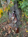
Got the shard glassed this weekend. Cut multiple grooves in the shard and the stock to give the acraglas some bite.
20240309_233324.jpg20240310_203710.jpg There was a a long splinter on the inside starboard, just below the broken piece extending all the way to where it meets the frame. It was barely hanging on and if removed would be very unsightly. So I took two flat pieces of metal coated with release agent and clamped to set up that area. You can just see a notch on the right in the second pic where there was a bit of wood missing around the splinter. I then went ahead and made a first pass with a cabinet scraper to remove the finish so I could see the grain pattern in order to match up my replacement piece on top. 20240310_203755.jpg20240310_203906.jpg There are two small blowouts right next to each other on the underside...either from the same loose stock problem that blew out the top, or from bubba trying to pry off the bottom plate. They are too small to fit a replacement piece, so I might just work some acra glass into the area. I'm not trying to hide the damage...just pass the 10ft stare test. A gun is only new once. There is also a gap under the front part of the tang, either from compression over the years, or maybe the top tang bent slightly from the force of opening with a loose stock. All of this will be corrected when I glass the recoil area of the frame. At the same time, I'll make sure some acra oozes up under the tang when everything is properly aligned. |
||||||
|
|
|
||||||
|
03-14-2024, 10:46 PM
|
#30 | ||||||
|
Looking up from the underside with the frame mounted to the stock, I can't see how it failed. Seems plenty of room. Then, before I glas my new block on top I decided to give a good soak this evening in a jar of acetone to get as much oil out of the end grain as I can. Big improvement after letting it sit for 4 hours or so. I mounted the frame again after letting it dry for a couple hours...and now I see it. The recoil nub is compressed, but the thin sidewalls had shriveled up greatly since the failure. Everything expanded slightly and things are tight. When I press to the rear, there appears to be some contact on the sidewalls, explaining the failure. Bedding the recoil nub with acraglas should fix it for another lifetime.
We will see how pretty the repair and refinishing turns out. Lots of dents that can be steamed out, but there are a few scrapes too deep to sand. My plan is to work the finish of the metal only until it matches the best condition of the stock I can get. The barrels are pretty much there now I think. Pitting underneath the frame has to go. One thing at a time. |
||||||
|
|
|
||||||
 |
|
|


 Linear Mode
